

Grain Flaker
The Challenge
Leverage simulation technology to optimize the design of a grain flaker
The Result
A functional grain flaker made from inexpensive, readily-available parts that rivals expensive commercial models
The details
Timeline: 2 weeks
Budget: $50
Course: Computer Aided-Design, Spring 2019
Skills used: CAD modeling (including parts for assembly), SolidWorks simulation, ShopBot, lathe, CNC milling machine
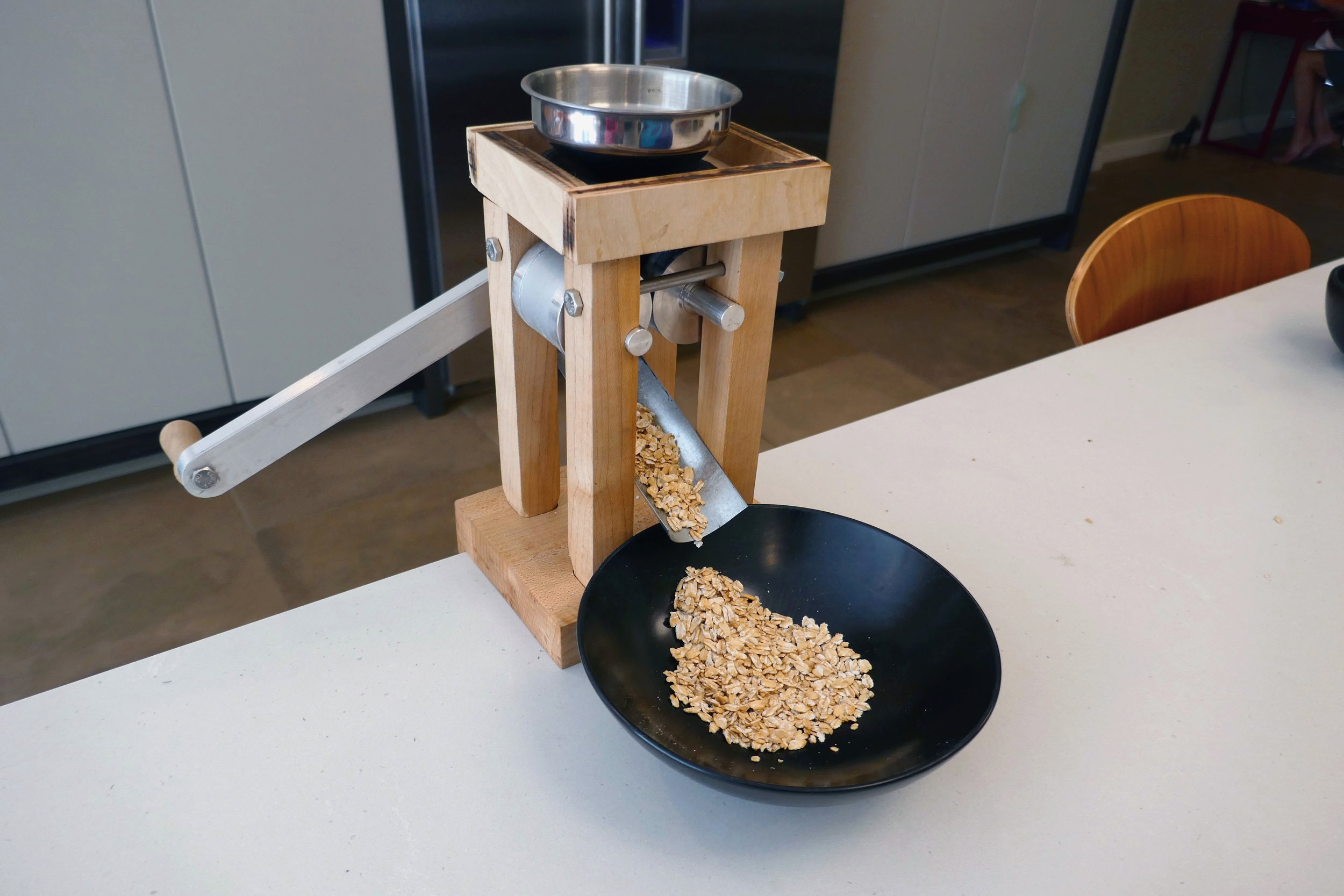
I designed and built this grain flaker as my final project for a Computer-Aided Design course, inspired by my fondness for overnight oats. Home-flaked oats are more nutritious, flavorful, and creamy than store-bought rolled oats.


Robust aluminum rollers, created from stock rod on the lathe, easily crush five grain groats at a time to an optimal thickness of 1/32”.

Tightening bolts above the rollers build adjustability and tolerance into the design. The black funnel attachment, created using mold and cavity tools within a SolidWorks assembly and 3D-printed from food-safe PLA, conforms perfectly to the rollers and eliminates grain spillage and mess.
How it works

Grain groats are poured into the funnel on top of the flaker. A 3D-printed attachment below the funnel feeds groats into the flaker.

A crank with a square hole attaches to a square driveshaft on one of the rollers. When the crank is turned, the rollers roll towards each other.

A 1/32” gap in the center of the rollers flattens groats as they are pressed between the two rollers.

Design Process
Digital Design


After modeling my rollers and funnel and adding them to the assembly, I used mold and cavity tools to create a 3D-printable funnel attachment that conforms to the rollers to prevent grain spillage.
I based my design on a few of the leading grain flakers on the market, including the Eschenfelder and Marcato Atlas models. Based on my budget and timeline, I strategically chose which parts to buy and which parts to make.
Simulation and analysis

The warmer-colored areas indicate higher stress levels.
In my first simulation, I analyzed normal forces on the pressing faces of the rollers. This was meant to simulate the outward force that a groat would exert on the roller as the roller flattens the groat. To choose the magnitude of my test force, I found a research paper that had tested the force needed to crush various species of rice. I estimated that my roller would crush a maximum of 5 groats at a time, and doubled the combined forces to be safe.
The simulation indicated that all parts had a high factor of safety in response to the normal force on the face of the rollers.

The warmer-colored areas indicate higher stress levels. The downward purple arrows represent the bearing load applied to the end of the crank.
For my next analysis, I simulated a downward force on the end of the crank to mimic the human-exerted force on the grain flaker. This simulation resulted in a large amount of stress on the square driveshaft of the driving roller, and led me to edit my design in order to increase the factor of safety. To decrease the stress concentration in this region, I increased the diameter of the driveshaft as well as the radius of curvature of the fillets on the square portion of the driveshaft.
Build Process

A mechanical drawing generated from a SolidWorks model of the driving roller. I originally planned to cut channels in the roller to help “catch” the grains, but I decided against it for ease of fabrication.

The flaker is easily disassembled, making for easy storage.
Materials and techniques used (by component):
Rollers: Aluminum; lathe and CNC milling machine
Base: Maple; ShopBot CNC, hand-finished
Legs: Maple; bandsaw, hand-finished
Top: Birch plywood; lasercutter
Chute: Aluminum; sheet metal shear
Funnel Attachment: PLA, 3D printer
Crank: CNC milling machine, manual milling machine, drill press
Funnel, fasteners, handle, and clamp were purchased.